A Modified Digital Elevation Modeling for Stormwater Management Planning in Segmentalized Micro-catchment Areas
- LeeEun-seok
- Received January 21, 2021; Revised January 24, 2021; Accepted January 28, 2021;
- ABSTRACT
-
- Background and objective: Urban topology can be characterized as impervious, which changes the hydrologic features of an area, increasing surface water flow during local heavy rain events. The pluvial flooding is also influenced by the vertical structures of the urban area. This study suggested a modified digital elevation model (DEM) to identify changes in urban hydrological conditions and segmentalized urban micro catchment areas using a geographical information system (GIS).
- Methods: This study suggests using a modified DEM creation process based on Rolling Ball Method concepts along with a GIS program. This method proposes adding realized urban vertical data to normal DEM data and simulating hydrological analyses based on RBM concepts. The most important aspect is the combination of the DEM with polygon data, which includes urban vertical data in three datasets: the contour polyline, the locations of buildings and roads, and the elevation point data from the DEM. DEM without vertical data (DCA) were compared with the DEM including vertical data (VCA) to analyze catchment areas in Shin-wol district, Seoul, Korea.
- Results: The DCA had 136 catchments, and the area of each catchment ranged from 3,406 m2 to 423,449 m2. The VCA had 2,963 catchments, with the area of each ranging from 50 m2 to 16,209 m2. The most important finding is that in the overlapped VCA; the boundary of areas directly affected by flooding and the direction of surface water flow could be identified. Flooding data from September 21, 2010 and July 27, 2011 in the Shin-wol district were applied as ground reference data. The finding is that in the overlapped VCA; the boundary of areas directly affected by flooding and the direction of surface water flow could be identified.
- Conclusion: The analysis of the area vulnerable to surface water flooding (SWF) was more accurately determined using the VCA than using the DCA.
- Introduction
- Introduction
Surface water flooding (SWF) is defined as when the surface water from a localized precipitation event exceeds the range of design criteria in a developed urban area due to heavy rainfall (Falconer et al., 2009; Houston et al., 2011; Kaźmierczak and Cavan, 2011; van Dijk et al., 2014). A main reason for the occurrence of SWF is the combination of backward flow due to exceeding the capacity of underground drainage systems, and overland flow due to the rapid saturation of ground surfaces (Boonya-Aroonnet et al., 2007; Golding, 2009; Hurford et al., 2012; Kaźmierczak and Cavan, 2011). SWF is inherently challenging to predict (Falconer et al., 2009; Houston et al., 2011; Kaźmierczak and Cavan, 2011). One of the major problems resulting from SWF is socioeconomic losses, such as damage to buildings and traffic systems, waterborne epidemics, and the disruption of public services (Hauger et al., 2006). In riverine urban areas, the scale of damage is particularly high when SWF occurs along with river flooding (Falconer et al., 2009). In addition, low-level areas of high density with poor water drainage systems are especially vulnerable to flooding during every rainy season (Kaźmierczak and Cavan, 2011).As stormwater management planning (SMP) is one of the main components of green infrastructure (GI) (Seamans, 2013), the GI target area must include green space, the catchment area, and river zones (Herlin, 2004). A review of a recent GI program found that it included a plan to physically control the storm water runoff at an urban scale (McLain et al., 2012; Montalto et al., 2012; Newell et al., 2013). In addition, the United States Environmental Protection Agency (USEPA) promotes the use of dispersal GI methods based on an environmental cost benefit of reducing stormwater flow and minimizing excess rainwater inflow to sewer systems (Evans, 2011; Keeley, 2011; Spatari et al., 2011).The spatial boundaries for efficient SMP are defined by catchment areas. SWF in urban areas essentially coincides with localized heavy rain due to the prevalence of impermeable surfaces (Boonya-Aroonnet et al., 2007). Therefore, the threshold values used in SWF prevention are characteristic of the catchment area and related to the SWF occurrence patterns (Hurford et al., 2012). Conventional urban structures and surface conditions are the main factors to consider when analyzing catchment areas with the goal of reducing the risk of SWF.Factors affecting the occurrence of SWF include buildings, street furniture, curb heights, and drainage capacity (Houston et al., 2011). These components interfere with water flow and make the area vulnerable to flooding compared with a non-urbanized area. In urban areas, water flows to the downslope area of the catchment surface during heavy rainfall. Due to the limited capacity of urban drainage systems, the presence of buildings and other vertical structures, and impermeable surfaces, flows tend to accumulate in low areas (Boonya-Aroonnet et al., 2007; Leitao et al., 2008). Due to the dense arrangement of structures in urban areas, the surface flow network in urban catchment areas tends to be narrow and complicated.A site scale is applied as an area unit in the re-analysis of catchment areas, as a basic geographic scale. Allen (2012) classified the spatial application size of GIs into a landscape, region, and site scale, and then proposed site scale as an appropriate unit for stormwater management. Therefore, catchment areas were re-analyzed by applying site scales as an area unit.High-resolution digital elevation models are useful for forecasting overland flow; however, they require additional technical development in order to be applied to urban flooding management (Boonya-Aroonnet et al., 2007). DEMs are widely available and use spatial analyses from GIS programs as input to prepare digital topographical maps. DEMs are also useful for identifying catchment areas based on overland flow, finding areas vulnerable to flooding, or simulating stream directions used by precision models (Prodanović et al., 2009). The addition of urban vertical data—such as curb heights, buildings, and walls—to a high-resolution DEM increases the precision of any analysis of overland flow and catchment areas. As artificial vertical structures are elements that affect overland flow in urban areas, urban vertical data are needed to fill the data gaps (Leitao et al., 2008; Leitao, 2013). Overland flow is caused by the flow of rainfall along road surfaces; it is affected by curbs, which keep the flow level at their height limit, block overflows, and guide the flow direction. Buildings, walls, and other vertical obstacles also influence overland flow because they stop or change the flow direction, as shown in Fig. 1. When overland flow meets vertical obstacles in a point of inflection of the topography, such as a slope-to-flat or a slope-to-slope area, ponds are formed. This indicates the initial occurrence of SWF caused by accumulated surface water and the backflow from over-flowing drainage systems (Boonya-Aroonnet et al., 2007).This research is conducted in order to discover areas vulnerable to flooding by analyzing surface water flow associated with micro-sub catchments and altered topography, both of which are the result of urbanization. This analysis is a necessary step prior to SMP. The purpose of this research is to propose a method for boundary area determination in order to implement efficient GI by applying vertical geo-information as a fundamental database. In addition, this research paper suggests a method for identifying appropriate locations for the implementation of efficient SMP and GI with the application of foundational vertical geo-information in an urban area.This study also presents the process required to add vertical geo-information data to a DEM. The results from the DEM combined with the vertical data could then be applied to development planning within a catchment area based on the rolling ball method (RBM) (Boonya-Aroonnet et al., 2007; Jenson and Domingue, 1988; Leitao, 2013; Maksimović et al., 2009; Prodanović, 1999; van Dijk et al., 2014; Zhou et al., 2010). In addition, the morphological differences of the catchment area in this study were shown by comparing the results from the DEM with and without the vertical data.
- Research Methods
- Research Methods
- Hydrological analysis
- Hydrological analysis
RBM is a hydrological model that simulates surface flow direction using elevation values from DEM cells. It can be used to identify connectivity or spillways, which are determined from an aspect-driven kinematic routing algorithm of the surface flow for every DEM cell (Boonya-Aroonnet et al., 2007; Lea, 1992; Leitao, 2013; Maksimović et al., 2009). RBM has a number of typical characteristics, including those shown in the results of work by Jenson and Domingue (1988). Jenson and Domingue (1988) developed a spatial analysis process for raster and vector data using mathematical approaches in FORTRAN. To be more specific, flow direction values were calculated by applying the DEM in the form of a revised Sink Cell. Codes ranging from two to 128 were automatically produced with a sequence of extracted square roots depending on the height variances of every DEM cell. The value of water accumulation was derived based on the code expressed with the square root of the direction value. Flow accumulation could then be calculated for every DEM pixel using the flow direction data and a conditional function. If a DEM cell contained water, it received a code number related to the flow direction of “1”, otherwise, it received a code number of “0”. Similarly, cells with the same direction code or showing accumulation received a water code of “1” from the neighboring cells. The code numbers were summed for each cell, and after multiple runs of the conditional function, flow accumulation data were given for every DEM cell.The complete hydrological analysis included watershed and sub-watershed analyses, watershed linkages, the drainage network, and the overland path (flow direction and combined flow accumulation) given by the DEM. The watershed analysis required both the flow direction and the DEM results for all “0” cells to obtain the catchment and watershed area and boundaries. The ArcGIS 10.1 hydrological analysis tool was used to ensure that the catchment area followed the watershed delineation methodology of Jenson and Domingue (1988). This study references the concept of Jenson and Domingue (1988) to suggest a process for producing baseline data for planning the installation of SMP.- Process development
- Process development
The main purpose of this study was to improve the method for identifying areas to reflect the vertical structures of urbanized land. To achieve this, this study suggests using a modified DEM creation process based on RBM concepts, along with a GIS program. This method proposes adding realized urban vertical data to normal DEM data and simulating hydrological analyses that followed RBM concepts. The most important aspect is the combination of the DEM with shape files (polygon data) that include urban vertical data in three datasets: the contour polyline, the locations of buildings and roads, and the elevation point data from the DEM. The process flowchart is shown in Fig. 2.- Creating the vertical DEM
- Creating the vertical DEM
The urban vertical data had to be calculated before it could be added to the BLDG and RD datasets. A new field “H” was created for each BLDG and RD point table, after which the RASTERVLU elevation was added to the urban vertical data using the “Field calculation” tool. Equations (1) and (2) below were used in the calculation:The building structure (e.g., the wall) was always assumed to have a positive value in Equation (1), as it was always above ground level, and the curb structure assumed a negative value in Equation (2), as most road structures are below ground level. It was possible to predict whether surface water flowed towards the entrance of a building by considering the flow direction of the latter. Therefore, a particular pattern of water flow direction behavior was discovered in this study, which focused on finding and interpreting the flow pattern of surface water.The water flux factors are only a minor part of this work, but could be useful in explaining how to determine water accumulative areas on the ground after water becomes a barrier. Furthermore, water flows downhill towards a road-side with a relatively low elevation when surface flow is blocked by constructed areas; this is one of the functions that roads have. Therefore, the direction of the surface water flow can be defined by increasing the height of the building and decreasing the elevation of the roads in the model.Given the short duration of SWF, the buildings are not vertically affected above the height of the first floor. Therefore, the “Building height” value used in Equation (1) corresponds to an average first-floor height based on the architectural regulations for the area of the study site. “Curb height” in Equation (2) followed the specifications of the road. The equations allowed the collection of point data for the vertical structure of the walls of the buildings and curbs, which could be used to make vertical TINs (Triangular Irregular Networks) with the contour polyline. The vertical TIN was converted to the vertical DEM using the “TIN to raster” tool. The input variation of the 2D resolution was 5 m × 5 m.- Study site
- Study site
While the method presented in this study is applicable to a broad range of areas, the watershed area of the Shin-wol district of Seoul, Korea was chosen for this case study. The target area of the Shin-wol district has a reputation for surface water flooding, following a rapid transformation from farmland to an urban area within 30 years. Thus, this area is appropriate for testing the hypothesis that rapid urbanization results in distortion and changes of geographical features.The study site was located south and west of Seoul, the capital of the Republic of Korea, and had an area of 6,411,100 m2. The population was 132,035 in 2010. The area was a typical agricultural region before the 1970s, which was when it started to become part of the urban sprawl area of Seoul, and radical changes occurred in just ten years (Fig. 3). The entire natural watershed area was urbanized and building density increased; many of the drainage systems built during the urbanization era are still in use. The increase in the impermeable surface area and the age of the drainage system both contribute to an increased vulnerability to SWF.In this area, SWF (i.e. sewage backflow flooding due to localized torrential rain) occurred on September 21, 2010 and on July 27, 2011. This study suggests a different stormwater management approach than the general plan proposed by the Seoul government, which focuses on increasing the outlet capacity. Application of the vertical DEM process can identify areas prone to SWF, and implementation in the watershed of the Shin-wol district can be examined.- Data sources
- Data sources
This study suggests a new process for identifying areas vulnerable to SWF in the Shin-wol district watershed. The new method combines urban vertical data with the DEM source. The simulation results of the DEM with and with out vertical data were compared using the same hydrological analysis. The data used in the analysis, established by the Korean government, can be seen in Table 1; it had a margin of error of 0.01 m. A digital map with a scale of 1:1,000 from the National Geographic Information Institute of Korea (NGIIK) was used to produce the DEM. Polygon data was provided by the NGIIK as road and building shape vector files, and the City of Seoul provided a flooding trace map based on survey data from 2010 to 2011 as a vector file.
- Results and Discussion
- Results and Discussion
- Comparison of the DEM with and without urban vertical data
- Comparison of the DEM with and without urban vertical data
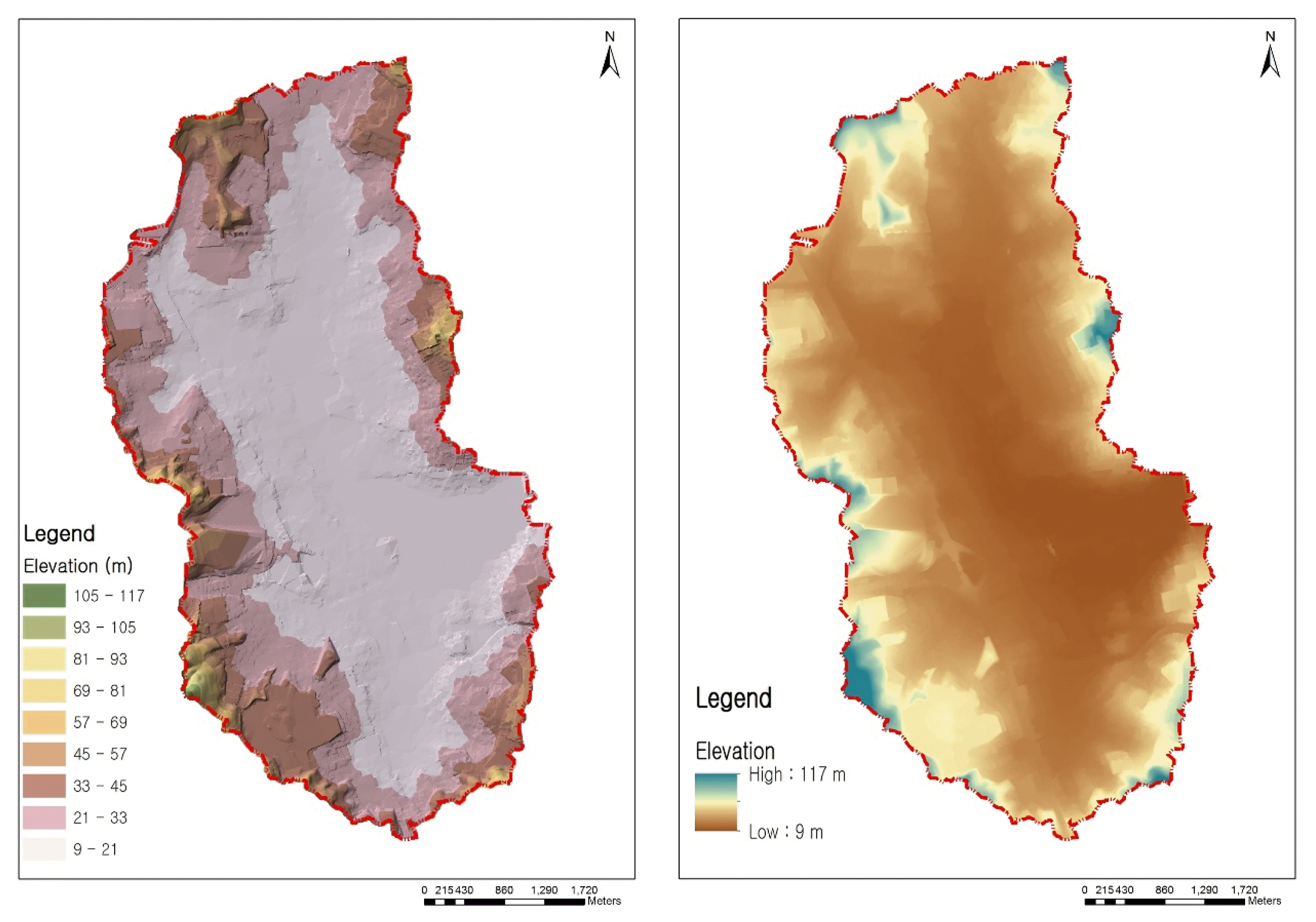
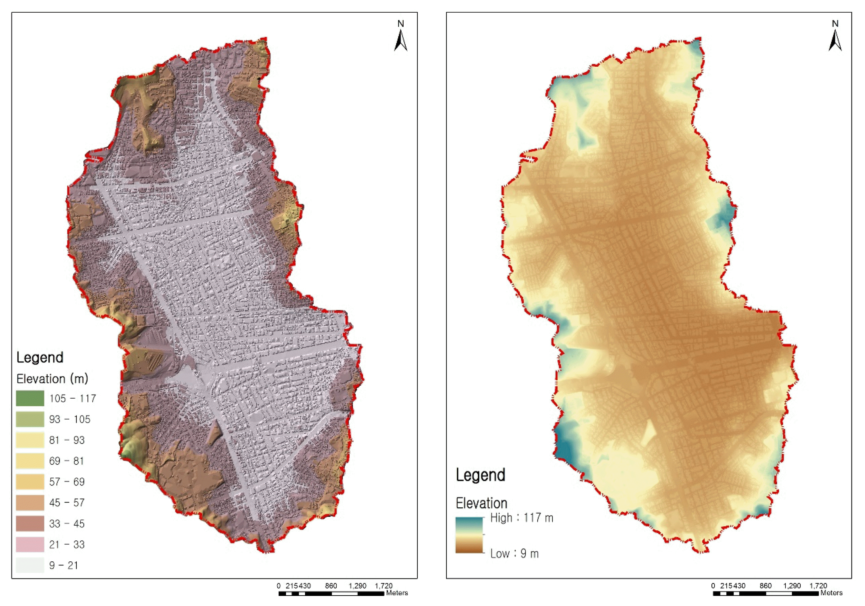
The TIN produced using the vertical data showed roads and clearer building locations (Fig. 5), in contrast to the DEM, which only used topography without urban vertical land data (Fig. 4). This was due to the Z factor of the contour, the 1 m level height of the buildings given in the BLDG points, and the 0.3 m depth of the road curbs in the road points when the TIN was formed. To obtain a detailed road surface using TIN, 3D forms should be added to the SHP using the program ArcScene.- Comparison of the hydrological analysis by rolling ball method
- Comparison of the hydrological analysis by rolling ball method
Catchment area
Catchment area
A comparison between catchment areas using the DEM without vertical data (DCA) and the DEM including vertical data (VCA) by the catchment delineation of the hydrological analysis based on RBM revealed a more detailed border for the VCA than for the DCA. This results from the fact that the VCA showed an integrated result including the topography, location of buildings, and depth of roads, while the DCA only included minor topography changes due to urbanization. The watershed of the urban area that was analyzed using the VCA showed features fragmented by roads and buildings, as shown in Fig. 5. For this process, a topographical DEM with a resolution of 1 m x 1 m was used to enter geographic data, and a vertical DEM with a resolution of 5 m x 5 m was used to analyze water flow.Catchment areas influencing the occurrence of SWF
Catchment areas influencing the occurrence of SWF
This study differentiated the DCA and VCA associated with flooding based on SWF trace maps of Seoul from 2010 and 2011 (SoSMG, 2014). This corresponded to the catchment areas directly affecting SWF, with their natural drainage points connected to the flooding area. The DCA had 136 catchments and the area of each catchment ranged from 3,406 m2 to 423,449 m2, indicating that a wide range of areas is potentially causing SWF. The VCA had 2,963 catchments, with the area of each ranging from 50 m2 to 16,209 m2; these are relatively small and detailed compared to the DCA areas. The detailed range of the catchment areas is shown in Fig. 6.In order to confirm that the catchment area results using the urban vertical data were directly affected by the flooding, DCA and VCA analyses results were applied equally to the 2010 and 2011 flooding areas. Compared with the DCA, which applied only the elevation data, the VCA, which applied the urban vertical data, showed clearer catchment areas, which were primarily related to the flooded area. Flooded areas are microscopically low in urban watersheds and are affected by upstream areas with subtle slopes. As shown in Fig. 7, the high-resolution VCA provides a clear picture of where the nearest upstream area affects the flooded area. The VCA results can be used as a basis for establishing systematic SMP in the micro-highlands for containment control and micro-lowlands for drainage reinforcement by identifying upstream areas that affect urban lowlands with repeated flooding damage.Surface water flow
Surface water flow
The differences between surface water flow using an application of the general DEM and the vertical DEM were compared in depth (Fig. 5). Surface water flow using the general DEM indicates that water flows along the direction of the contour, regardless of any vertical structure. The result of surface water flow using the general DEM only takes into account the surface flow tending towards a flooding area. However, surface water flow analyzed by vertical DEM shows the flow along vertical structures. This result indicates that the flow started at a building complex or a natural area and flowed into roads. This indicates that the feature is almost aligned with the real surface flow in an urban area along the roads.The most important finding is that in the overlapped VCA; the boundary of areas directly affected by flooding and the direction of surface water flow could be identified. The catchment area can be divided into areas that directly influence flooding and areas that indirectly influence flooding, which are shown as the light blue areas and the white areas in Fig. 8. (b), respectively. An area indirectly influences flooding when the rainwater accumulates on the surface of the ground before being transferred to an area that directly influences flooding.This study enabled the differentiation between areas that directly/indirectly influenced flooding. Moreover, the direction of surface water flow could assist in verifying the surface water connectivity to urban surface water flooding.
- Conclusion
- Conclusion
The purpose of the process developed in this study to produce a vertical DEM was to compare the simulation results of surface water flow using only topographical data against the inclusion of urban vertical structure information. This process helps to identify possible applications of GIP in conventional urban areas, and is clearly useful for SMP.The VCA resulting from this process revealed a fragmented small basin and could simulate the surface flow along roads for each catchment area, showing flow characteristics such as the starting point, accumulation location, flow path according to topography, and flow concentration at the outlet point.When applied to flooded urban locations, the small basins near vertical structures could be separated into catchment areas affecting the flooding. In the catchment areas that directly influenced the flooding, direct accumulation was combined with surface water from the other catchment areas, which frequently occurred around larger roads. These areas showed an accumulated volume of surface water. Therefore, measures to delay the increased residence time should be applied to reduce flooding vulnerability. The catchment areas indirectly influencing the flooding represented the starting points of the surface water spill caused by rain, with their surface water being transferred to the adjacent catchments. Therefore, a planned approach to reduce the surface water spill within the catchment area and to minimize the transfer to the adjacent catchments is needed. The use of this process to perform SMP will reduce the vulnerability to SWF in established urban areas regardless of the site scale, by providing solutions that are more effective.This study has two main limitations. The first is that the process cannot calculate the increased residence time, flow rates, and flow velocities, as the analyses are based on GIS hydrological principles and simulate the geographic relationship based on geographic information. Secondly, due to the time range of this study information regarding the underground pipe network was not included, which only includes the malfunction of the underground drainage system. To investigate the causes of SWF and to simulate it dynamically, the underground pipe network must be included, and high-end tools like SWMM 5, XP-SWMM, and STORM are recommended. This research paper suggests optimized methods of applying the vertical structure of DEM with an ArcGIS process. The paper intends to identify a spatial base unit based on the pattern of surface water flow, in order to show a specified urban map with the purpose of controlling urban surface water flow through applying a more useable ArcGIS process.These results suggest that further studies are needed to establish a planning process that can be applied to catchment areas that influence SWF. A recovery plan for intra-area waterways based on an understanding of surface water flow characteristics is another possible application. This research aims to make SMP and GIP applicable in any city, and to provide a resource that other cities can utilize when planning green infrastructure.
Fig. 1
Differences in the vertical structure (red dotted line) and water flow (blue arrow) between the natural land condition (top) and urban land condition (bottom).
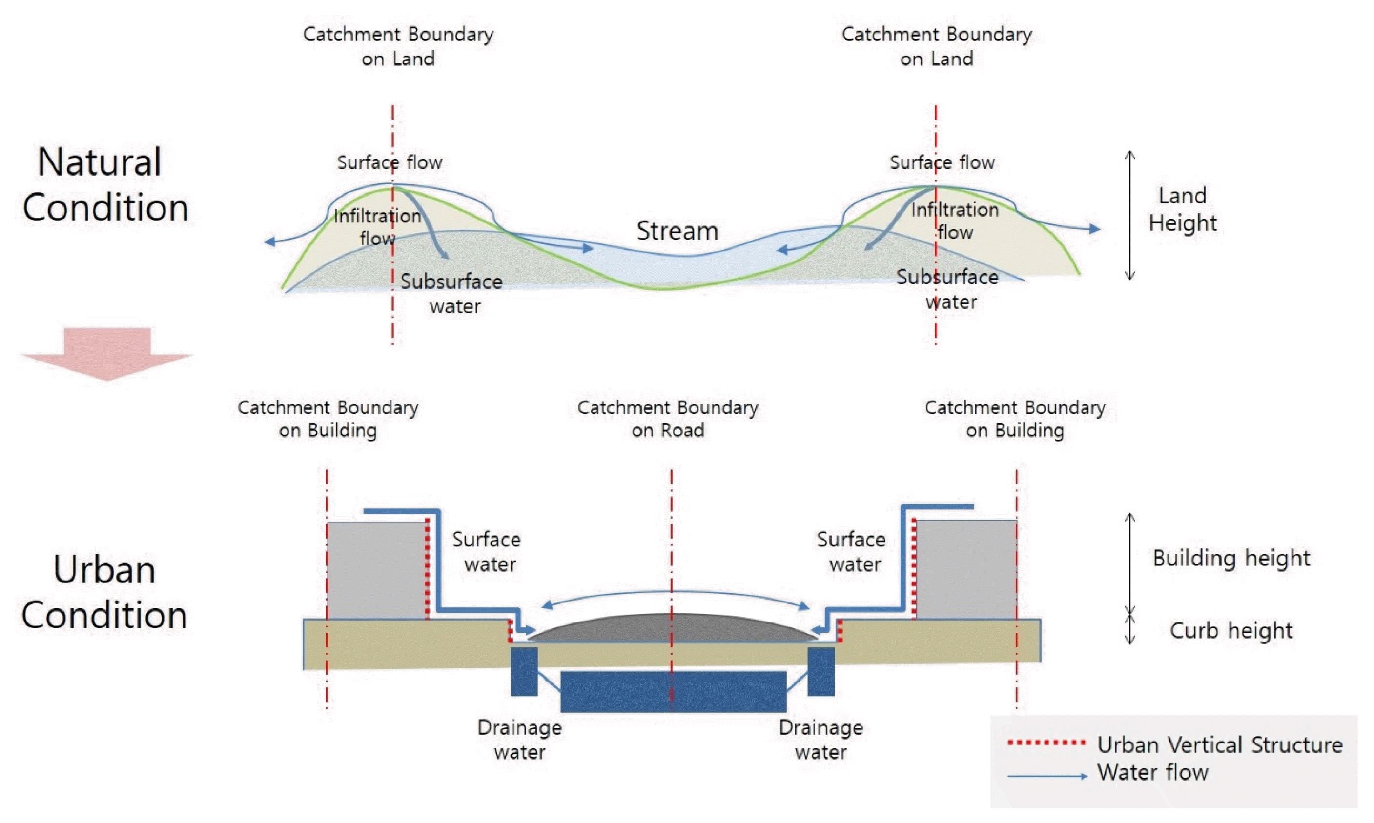
Fig. 2
Modified GIS process for making a DEM with vertical geo-information (gray colored box) reflecting urban vertical land structure and general hydrological analyses using ArcGIS 10.1.
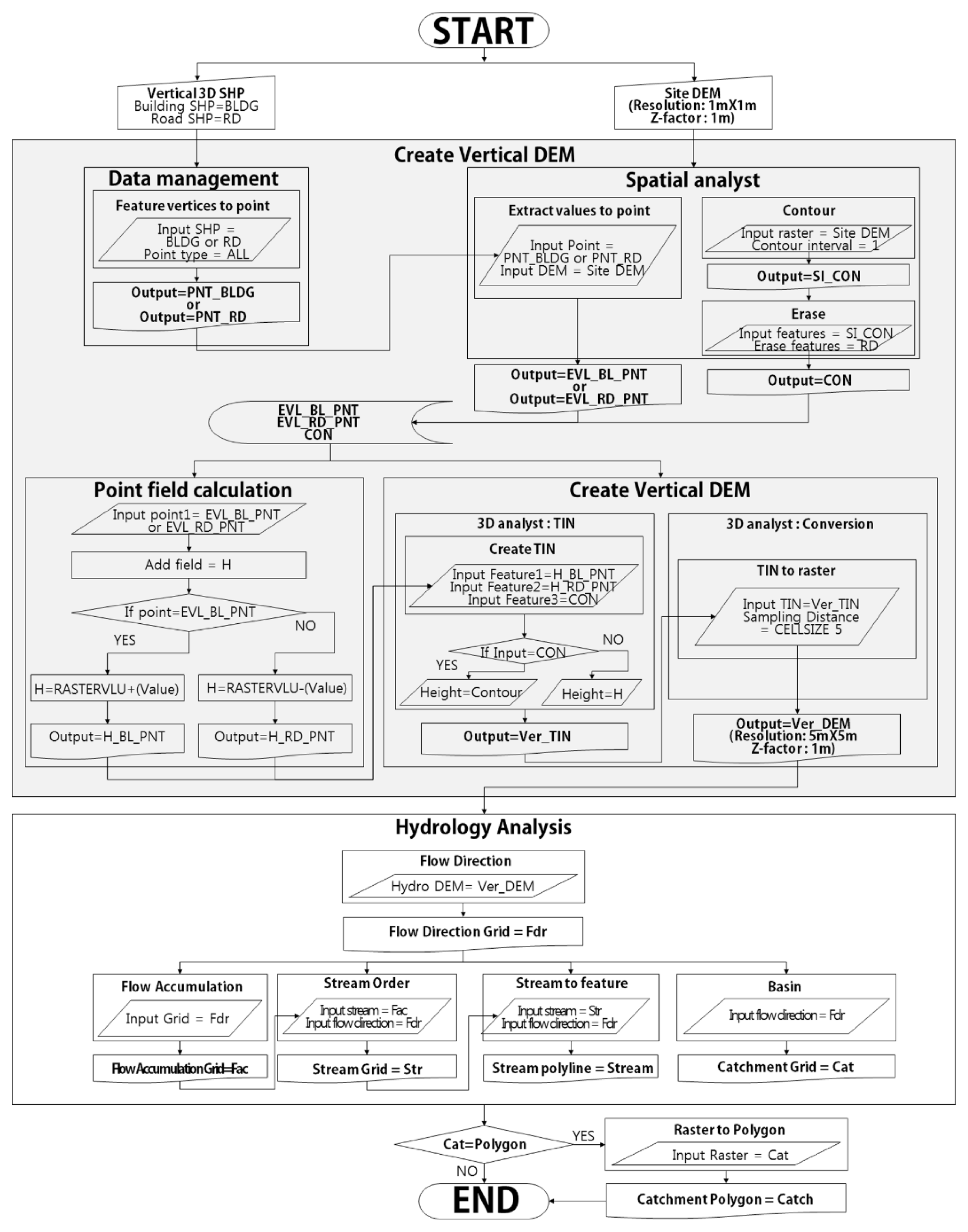
Fig. 3
Comparisons of radical urbanization of the study site. (a) 1972 (b) 1978; (c) the geographical characteristics of the watershed area of the Sin-wol district; (d) CCTV footage from September 21, 2010 showing surface water floods in the watershed area of Sin-wol.

Fig. 6
Comparison between the (a) DEM without vertical data (DCA) and the (b) DEM including vertical land data (VCA). Note the different catchment areas, shapes, and sizes resulting from the two methods.
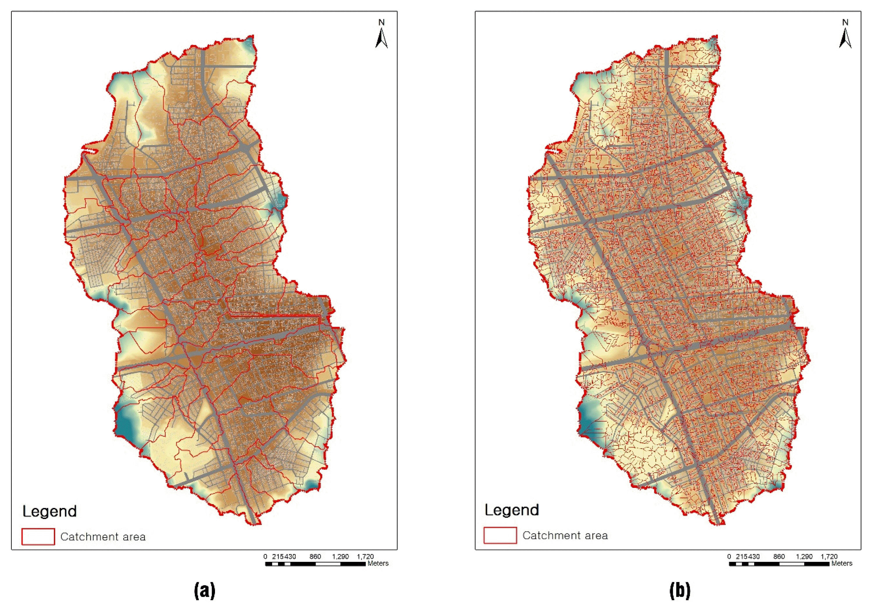
Fig. 7
Difference in the resolution of the catchment areas influencing the surface water flooding given by the (a) the DEM without urban vertical data (DCA) and (b) the DEM including urban land vertical data (VCA).
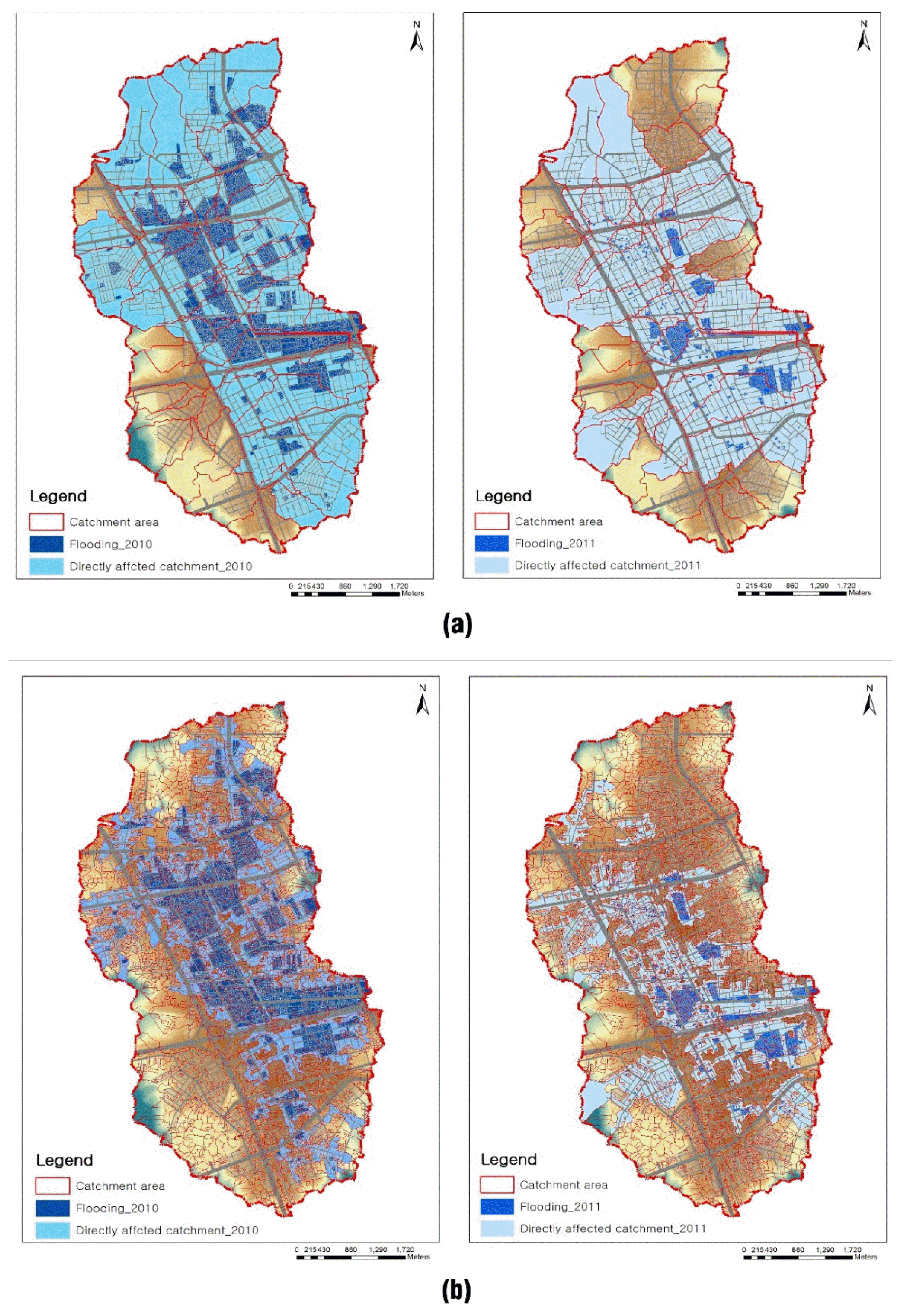
Fig. 8
Comparison of surface water flow results with general DEM and vertical DEM Flow line analyzed by general DEM shows the direction regardless of urban structure (a); Surface water flow line analyzed using a vertical DEM shows its directional nature, with flow accumulation reflecting urban structure (b).

Table 1
Data sources used to make the vertical DEM in this study
- REFERENCES
- REFERENCES
References
Ahmed, S, M Meenar, A Alam. 2019. Designing a blue-green infrastructure (BGI) network: toward water-sensitive urban growth planning in Dhaka, Bangladesh. Land. 8(9):138.https://doi.org/10.3390/land8090138
[Article]Allen, WL III 2012. Environmental reviews and case studies: Advancing green infrastructure at all scales: From landscape to site. Environ Pract. 14(1):17-25. https://doi.org/10.1017/S1466046611000469
[Article]Boonya-Aroonnet, S, C Maksimovic, D Prodanovic, S Djordjevic. 2007 Urban pluvial flooding: development of GIS based pathway model for surface flooding and interface with surcharged sewer model. NOVATECH 2007 Retrieved from http://documents.irevues.inist.fr/bitstream/handle/2042/25252/0481_040boonya.pdf?sequence=1.Congalton, RG 1991. A review of assessing the accuracy of classifications of remotely sensed data. Remote Sens Environ. 37(1):35-46. https://doi.org/10.1016/0034-4257(91)90048-B
[Article]Congalton, RG, RA Mead,. 1983. A quantitative method to test for consistency and correctness in photointerpretation. Photogramm Eng Remote Sensing. 49(1):69-74.Christman, Z, M Meenar, L Mandarano, K Hearing. 2018. Prioritizing suitable locations for green stormwater infrastructure based on social factors in Philadelphia. Land. 7(4):145.https://doi.org/10.3390/land7040145
[Article]Evans, JP 2011. Resilience, ecology and adaptation in the experimental city. Trans Inst Br Geogr. 36(2):223-237. https://doi.org/10.1111/j.1475-5661.2010.00420.x
[Article]Falconer, RH, D Cobby, P Smyth, G Astle, J Dent, B Golding. 2009. Pluvial flooding: new approaches in flood warning, mapping and risk management. J Flood Risk Manag. 2(3):198-208. https://doi.org/10.1111/j.1753-318X.2009.01034.x
[Article]Foody, GM 2002. Status of land cover classification accuracy assessment. Remote Sens Environ. 80(1):185-201. https://doi.org/10.1016/S0034-4257(01)00295-4
[Article]Golding, BW 2009. Long lead time flood warnings: reality or fantasy? Meteorol Appl. 16(1):3-12. https://doi.org/10.1002/met.123
[Article]Hauger, MB, JM Mouchel, PS Mikkelsen. 2006. Indicators of hazard, vulnerability and risk in urban drainage. Water Sci Technol. 54(6–7):441-450. https://doi.org/10.2166/wst.2006.622
[Article] [PubMed]Herlin, IS 2004. New challenges in the field of spatial planning: Landscapes. Landsc Res. 29(4):399-411. https://doi.org/10.1080/0142639042000289037
[Article]Houston, D, A Werrity, D Bassett, A Geddes, A Hoolachan, M McMillan. 2011 Pluvial (rain-related) flooding in urban areas: the invisible hazard Joseph Rowntree Foundation; Retrieved from https://www.jrf.org.uk/report/pluvial-rain-related-flooding-urban-areas-invisible-hazard.Hurford, AP, SJ Priest, DJ Parker, DM Lumbroso. 2012. The effectiveness of extreme rainfall alerts in predicting surface water flooding in England and Wales. Int J Climatol. 32(11):1768-1774. https://doi.org/10.1002/joc.2391
[Article]Jenson, SK, JO Domingue. 1988. Extracting topographic structure from digital elevation data for geographic information system analysis. Photogramm Eng Remote Sensing. 54(11):1593-1600.Kaźmierczak, A, G Cavan. 2011. Surface water flooding risk to urban communities: Analysis of vulnerability, hazard and exposure. Landsc Urban Plan. 103(2):185-197. https://doi.org/10.1016/j.landurbplan.2011.07.008
[Article]Keeley, M 2011. The Green Area Ratio: an urban site sustainability metric. J Environ Manage. 54(7):937-958. https://doi.org/10.1080/09640568.2010.547681
[Article]Landis, JR, GG Koch. 1977. The measurement of observer agreement for categorical data. Biometrics. 33(1):159-174. https://doi.org/10.2307/2529310
[Article] [PubMed]Lea, NJ 1992 An aspect-driven kinematic routing algorithm. Overland Flow 389-403. London, UK. CRC Press; Retrieved from https://www.scirp.org/(S(351jmbntvnsjt1aadkposzje))/reference/ReferencesPapers.aspx?ReferenceID=1256774.
[Article]Leitão, JP, D Prodanović, S Boonya-aroonnet, Č Maksimović. 2008 Influence of DEM resolution on surface flow network for pluvial urban flooding and simulations of integrated system. In: Proceedings of Research, 11th International Conference on Urban Drainage; 1-11. Edinburgh, Scotland. UK; Retrieved from http://tiwrm.haii.or.th/web/attachments/301_Influence%20of%20DEM%20resolution%20on%20surface%20flow%20network%20for%20pluvial.pdf.Leitao, JP, D Prodanović, S Boonya-aroonnet, Č Maksimović. 2013. Enhanced DEM-based flow path delineation methods for urban flood modelling. J Hydroin formatics. 15(2):568-579. https://doi.org/10.2166/hydro.2012.275
[Article]Maksimović, Č, D Prodanović, S Boonya-Aroonnet, JP Leitão, S Djordjević, R Allitt. 2009. Overland flow and pathway analysis for modelling of urban pluvial flooding. J Hydraul Res. 47(4):512-523. https://doi.org/10.1080/00221686.2009.9522027
[Article]McLain, R, P Melissa, PT Hurley, J Lecompte-Mastenbrook, MR Emery. 2012. Producing edible landscapes in Seattle's urban forest. Urban For Urban Green. 11(2):187-194. https://doi.org/10.1016/j.ufug.2011.12.002
[Article]Montalto, FA, TA Bartrand, AM Waldman, KA Travaline, CH Loomis, C McAfee, JM Geldi, GJ Riggall, LM Boles. 2013. Decentralised green infrastructure: the importance of stakeholder behaviour in determining spatial and temporal outcomes. Struct Infrastruct Eng. 9(12):1187-1205. https://doi.org/10.1080/15732479.2012.671834
[Article]Newell, JP, M Seymour, T Yee, J Renteria, T Longcore, JR Wolch, A Shishkovsky. 2013. Green Alley Programs: Planning for a sustainable urban infrastructure? Cities. 31:144-155. https://doi.org/10.1016/j.cities.2012.07.004
[Article]Paine, DP, JD Kiser. 2003 Chapter 23: Mapping accuracy assessment 465-480. New York, USA. John Wiley & Sons; Retrieved from https://www.researchgate.net/profile/Stephen_Stehman/publication/260138066_Statistical_Rigor_and_Practical_Utility_in_Thematic_Map_Accuracy_Assessment/links/56f13e2e08aec63f4c9b511a.pdf.Prodanović, D 1999 Improvement of the methods for the hydroinformatics application in urban runoff analysis. Doctoral dissertation Faculty of Civil Engineering, University of Belgrade; Belgrade. Serbian. Retrieved from https://grafar.grf.bg.ac.rs/handle/123456789/1778.Prodanović, D, M Stanić,, V Milivojević, Z Simić, M Arsić. 2009. DEM-based GIS algorithms for automatic creation of hydrological models data. J Serbian Soc Comput Mech. 3(1):64-85.Rosenfield, GH, K Fitzpatrick-Lins. 1986. A coefficient of agreement as a measure of thematic classification accuracy. Photogramm Eng Remote Sensing. 52(2):223-227.Safety of Seoul Metropolitan Government (SoSMG)2014 November 4 Digital Maps Retrieved from http://safecity.seoul.go.kr:8070/scmyn_cf/map/cfMap.do?type=ds_area#. Accessed 4 November 2014Seamans, GS 2013. Mainstreaming the environmental benefits of street trees. Urban For Urban Green. 12(1):2-11. https://doi.org/10.1016/j.ufug.2012.08.004
[Article]Sohn, W, SD Brody, JH Kim, MH Li. 2020. How effective are drainage systems in mitigating flood losses? Cities. 107:102917.https://doi.org/10.1016/j.cities.2020.102917
[Article]Sohn, W, JH Kim, MH Li, R Brown. 2019. The influence of climate on the effectiveness of low impact development: A systematic review. J Environ Manage. 236:365-379. https://doi.org/10.1016/j.jenvman.2018.11.041
[Article] [PubMed]Sohn, W, JH Kim, MH Li, R Brown, FH Jaber. 2020. How does increasing impervious surfaces affect urban flooding in response to climate variability? Ecol Indic. 118:106774.https://doi.org/10.1016/j.ecolind.2020.106774
[Article]Spatari, S, Z Yu, FA Montalto. 2011. Life cycle implications of urban green infrastructure. Environmental Pollution. 159(8–9):2174-2179. https://doi.org/10.1016/j.envpol.2011.01.015
[Article] [PubMed]van Dijk, E, J van der Meulen, J Kluck, JHM Straatman. 2014. Comparing modelling techniques for analysing urban pluvial flooding. Water Sci Technol. 69(2):305-311. https://doi.org/10.2166/wst.2013.699
[Article] [PubMed]Zhou, Y, Y Wang, AJ Gold, PV August. 2010. Modeling watershed rainfall-runoff relations using impervious surface-area data with high spatial resolution. Hydrogeol J. 18(6):1413-1423.
[Article]

